|
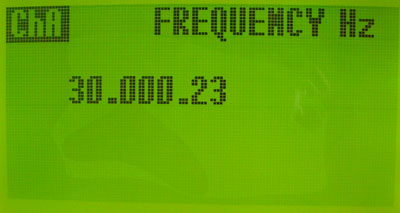
PM5: Dual Channel 500MHZ RF
Meter with 30MHZ Frequency Counter
Project by:
Tony / I2TZK,
Frank
/ K7SFN , Dinesh / VU2FD

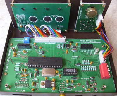
GCPUx is an expandable CPU and Graphic LCD
project which has provision to "add" a "project"
board to create a full function amateur radio station accessory.
Advantage of concept "GCPUx" is a
possibility to add new project board to GCPUx, change processor code
and create a new working unit for ham station.
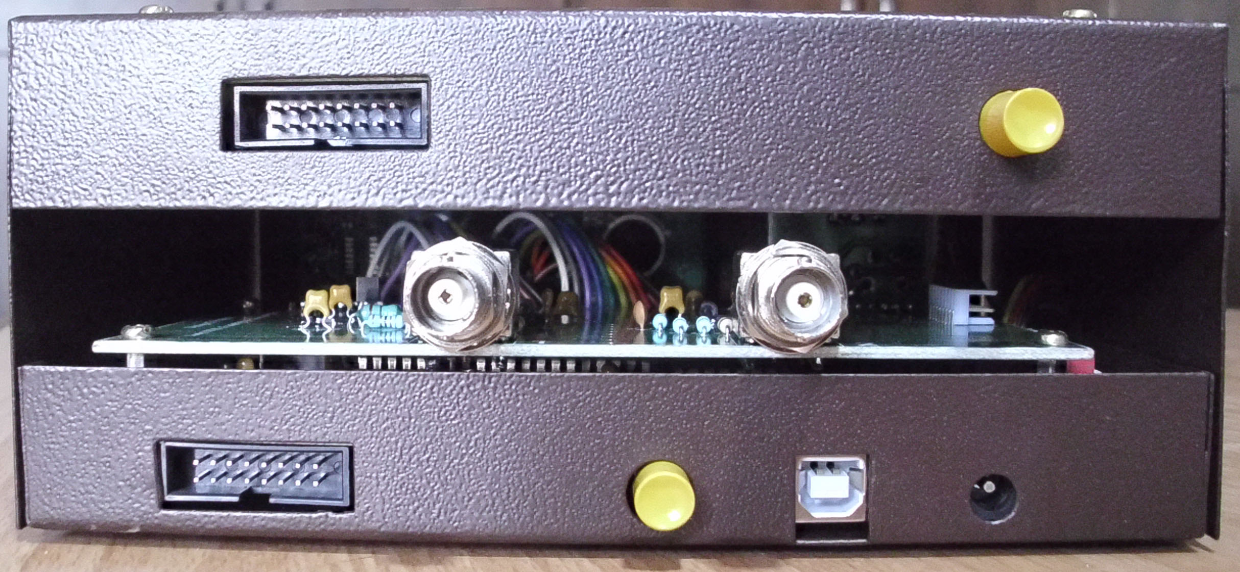
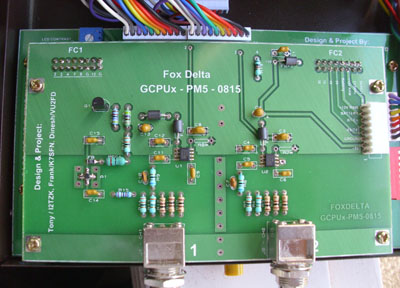
PM5 is AD8307 based RF meter to 500MHZ. This
"add-on" project board fits on top of GCPUx main board to
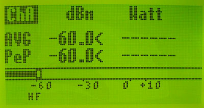
create a 2 Channel 500MHZ RF Meter. Measurement results are
displayed on 128X64 Graphic LCD. A PC program will be availble too.
A
battery board is included with this kit. You may use a NiMh or NiCad
batteries with 7.2V output. Battery (NiMH or NiCad) not included as
not allowed by postal department.
|
PM5:
|
|
|
|
|
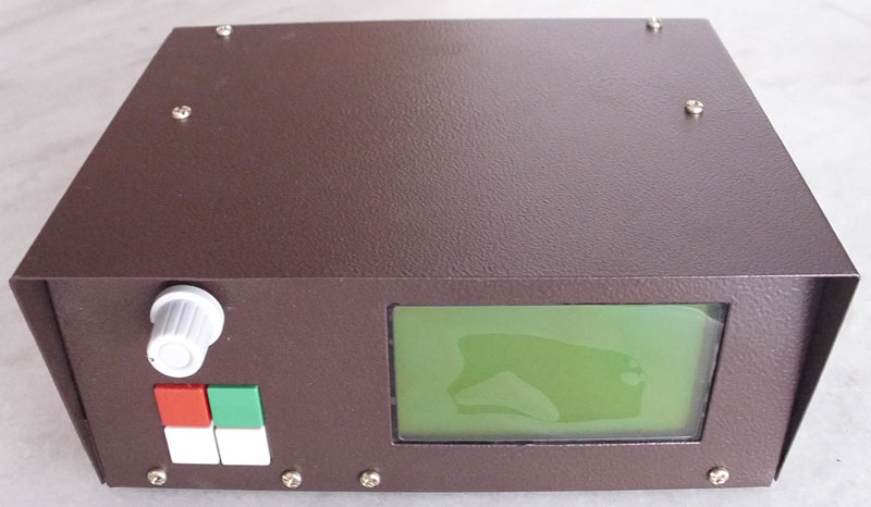
GCPUx
Main Board with metal case |
 |
| Click to enlarge
|
|
|
|
GCPUx main
board with PM5 :add-on" Board:
|
|
|
Click to enlarge
|
|